For more pictures and diagrams of the inner workings, visit the gallery.
TIM 8 only took a few weeks to design. This was mainly because I'd worked out all the hard while stuff designing TIM 7. The problem was I'd now found all the relays there were to be found, and that only came up to about 150. I've never seen an 8 bit relay computer built in less than 281 relays, and most of those were 4 pole relay, where as mine are nearly all single pole. So I had to take the simplification to extreme lengths. The advantage of running it straight off the tape reader is that you didn't require a program counter, or a finite state machine, or a clock, which saves a good hundred relays at least. Then there is the serial ALU, which although is much slower than a parallel one, allows greater flexibility and uses far less relays.
Just to clarify, 'ALU' stands for 'Arithmetic Logic Unit'. The ALU in TIM 8 does all 8 logic processes for the computer, so is basically TIM's brain. It took a long time and a lot of effort to get it down to just 12 relays (The one on TIM 7 would have used 40), However it does require the parallel to serial converters and command selector etc. which brings the relay count up slightly, but it's still pretty small. The 1 bit nature of the ALU does allow useful tricks such as variable bit width, so you can string 2 or more registers together if you need to process numbers greater than 8 bit. Alternatively, you could use half a register for one 4 bit number, and the other half for another to increase memory capacity when dealing with small numbers.
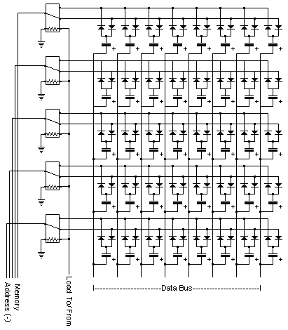
Another problem that had occurred was that I refuse to use a RAM chip for memory, because it's a RELAY computer, not a relay-with-several-million-transistors-thrown-in-because-I'm-to-lazy-to-do-it-properly computer. As such I'm only really allowing technology which was around before the time of ENIAC. Almost every other relay computer I've seen uses a RAM chip, which is only vaguely acceptable as they're using the Von Neumann Architecture (Computer data and program are stored in the same memory) , where as I'm using the Harvard Architecture (Computer data and program are stored in separate memories, in my case the program is stored on the punch tape). This means the amount of memory I have doesn't limit the length of program I can write, however it still limits the amount of data the computer can process. So I designed in five 8 bit registers. But that uses a huge amount of relays and only stores 5 bytes, which isn't really enough for anything exciting. I had also just redesigned my memory addressing system so that it allowed 16 bytes of memory to be stored. The problem was now that I had very few relays left, so making all of that out of relay latch memory wasn't possible. I therefore set about researching all the different kinds of computer RAM that had ever been developed to try find one which I could use, however they all were horribly complex and required large amounts of decoding hardware. So I had to design my own. I decided to use capacitors as they were the only component I had which could store data easily. So I spent the next week or so trying loads of different designs out, looking at the problems encountered and redesigning accordingly. Eventually I came up with the following design, which only uses one relay pole per byte:
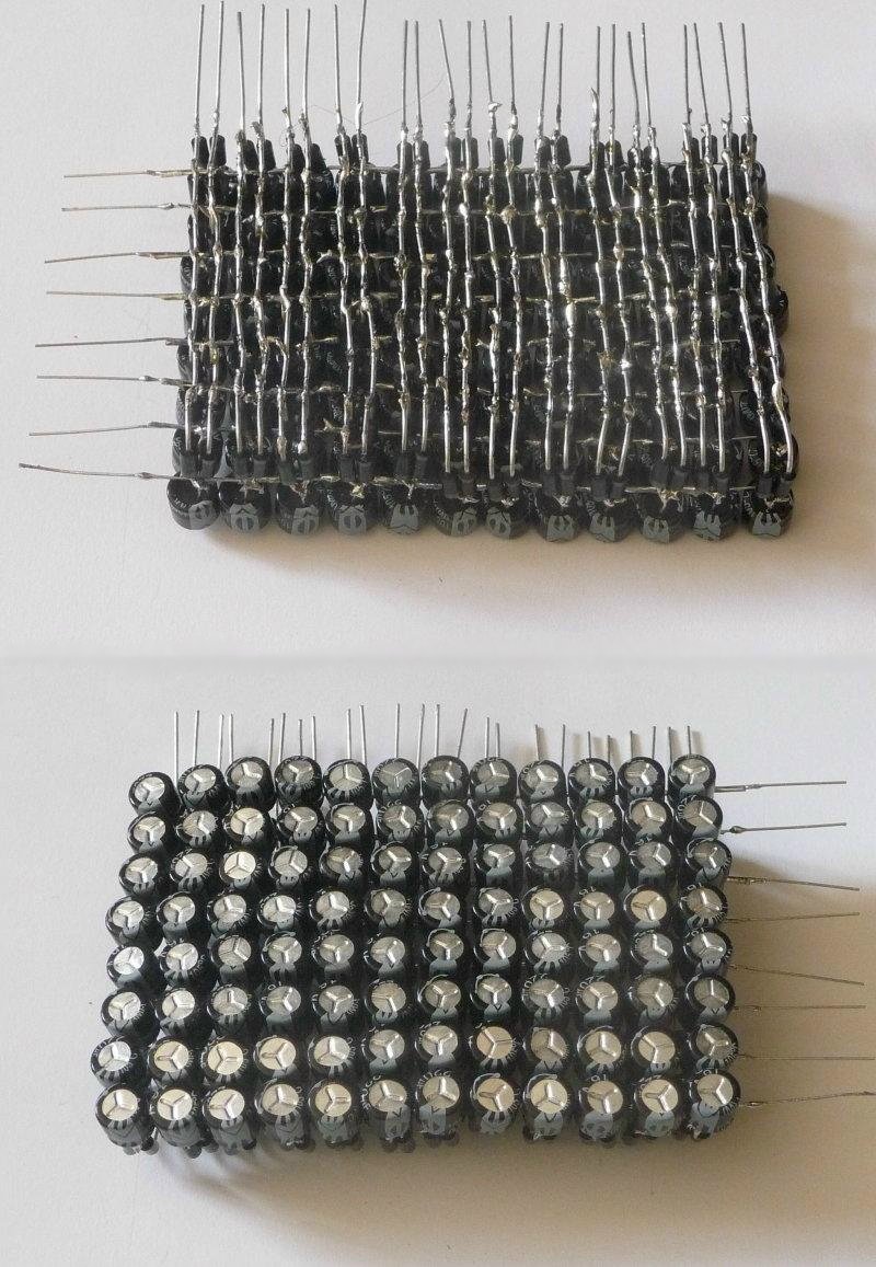
This meant I could now use all of my addressable memory with out having to resort to modern IC's. It did mean I had to buy around 100 capacitors and 200 diodes, but they are much cheaper than relays, and I think the total cost of the memory was around �10. I first made a quick test set up of 2x2 bits, which fortunately worked exactly as I predicted. You can see it in this video. So I started to work on the main memory, which is 12 bytes. 4 evenings of hard soldering later, and it was finished. It would probably have taken far longer. if it was not for the mass production tecnique i used for it. The finished memory block is shown below. It has been installed and debugged, and works fine apart from memory location 5, but that's due to a dodgy relay in the addressing circuitry which i can't easily get at to fix.
Another interesting little development is that I may fit another 16 bytes of ROM in the form of dip switches, which could be used as a look up table for things like 7 segment displays. It also means it's even more similar to the Harvard Mark-I computer on which TIM appears to be based but isn't actually (It was a while after I had finished the design that I researched the Mark-I). These dip switches would share the same address bus as the memory, but would require a 12V pulse rather than a 0V one that the memory requires. This means it only requires a 10 extra relays to implement.
To see the full circuit diagram click here.
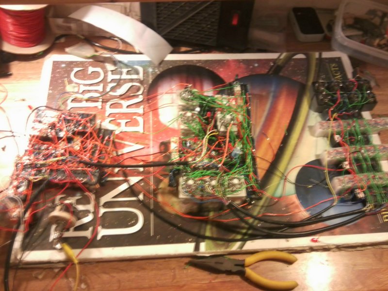
Below is (quite a poor) photo of an almost completed T.I.M. on my desk. I had to build it on the sheets which eventually became the case, or it would have been very hard to make it fit:
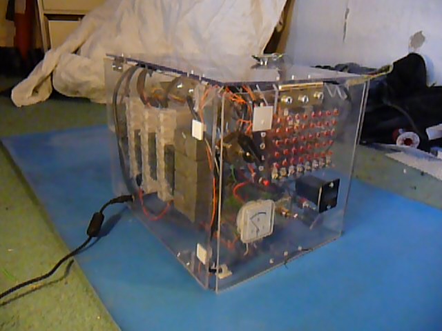
This is one of an almost completed T.I.M. in his box. From the photo above to the photo below was about one school week. This rapid development was due to the fact I had heard there was to be a science fair that Friday, and decided it would be a good deadline in which to finish TIM, or it would never get done. Some very late nights later and TIM was pretty much done. I took it into school the next day almost entirely untested, and after an hour trying to fix a fault (turned out the tape reader head had moved slightly), it ran an increment program for 2 hours continuously without fault (We eventually turned it off, the clicking was driving us insane). Admittedly the increment command was all he could do at that point, seeing as I had wired up the A and B inputs to the ALU the wrong way round, but I only discovered that the next day.
One of the aims of the TIM project was to construct a Turing complete computer using the smallest amount of relays I could. The total relay count currently stands at 152, but those are mostly single pole relays, and doesn't give a fair comparison when comparing to the counts of other relay computers such as Harry porters, which uses 415 4 relays, which makes it sound like TIM is only 3 times smaller. But much more can be done with a 4 pole relay than with a single pole relay, so I count the computer's size in relay poles. Tim currently uses only 219 poles, where as by comparison Harry's uses 1660 poles, which makes TIM eight times smaller. I believe it is one of the& smallest Turing complete relay computers in the world by relay count (with maybe the exception of the 'DUO Premium'). I could make it substantially smaller by reducing the amount of registers, or making it 4 bit instead of 8, but then that would greatly limit the amount I could do with it, and I didn't want to spend a year on a project that was ENTIRELY useless :P
To see a video of it running, click here.
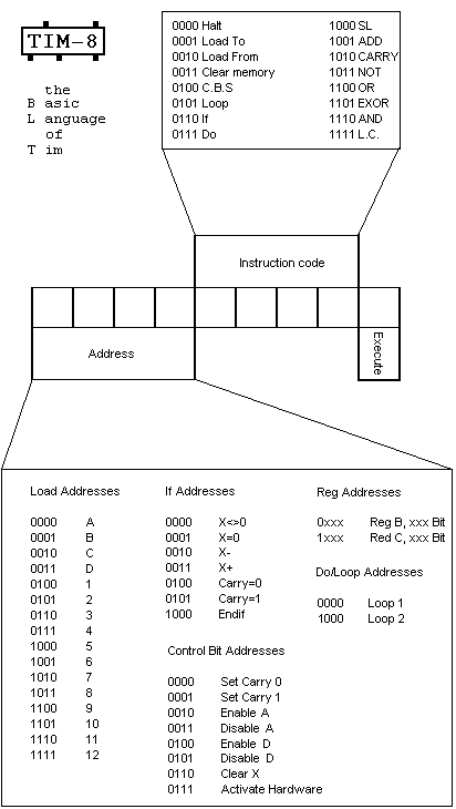
The BIOS of T.I.M. is called B.L.T. (Basic Language of Tim/ My favourite sandwich). It is designed in the way to use the smallest possible amount of relays for decoding, and yet keep it Turing complete. It's fairly basic, but is still surprisingly flexible. As the ALU is serial, each bit has to be addressed seperately to pass through it. This means you have 8 commands for any ALU instruction. This may seem excessive, but it means that for example if I wanted to store two 4 bit numbers separately, I could store them in the same register or alternatively, as the carry has it's own register and is fed back in to each computation, I can link registers together to hold larger numbers. So with T.I.M.'s 16 bytes of memory (including registers), it should be able to hold numbers equivalent to around 3.4x10^38... which is pretty big (128 bits). However, for addressing commands you only need a 3 bit address, and the address in is 4 bits across. Therefore I've used this to allow me to address to working registers (B and C) which means I can work on more numbers where they are instead of having to move them into a different memory location (which there are very few of). This means that if I was counting using a flag (for example) then I could increment my flag in one register, and do all the workings in the other.
I have also left out commands I can do in other ways using more commands. E.G. there is no INC command as this would take an extra command and be hard to do on a serial ALU. However to increment you 'set carry to 1', 'Disable input A' and then ADD A and B to increment B. Again this means the computer is more flexible as you can increment single digits or huge numbers with much less relays. Despite being so simple I'm always having to update the language where I've hardwired it into T.I.M. wrong or written it down wrong. For example none of my more complex programs worked previously, and this was because I'd written down 'Disable input A' as 'Disable input B/C' which meant I was always trying to increment A which won't work.
Another thing I did to save relays was doing away with the clock and finite state machine that times all the commands in the computer. If you look at the tape, the commands are much longer than the execute line to let the relays settle in the right position before a command is processed. To do any other timings I have used capacitors. This reduces the speed I can run the computer, but speed wasn't what T.I.M. was designed for.
Here is a picture explaining the language:
To make programs simpler to write, I have written up a little assembler language which I call T++. It takes the text text description of each command
and converts it into the binary equvilent. It also will convert a singal ALU command into a string of commands required to do the operation. I have also added functions to it, so if you type say, 'subtract a b', it will put the nessasary code in to subtact A from B. For a full list of comands, visit the gallery.
I have written a few programs now, including one that almost amounts to an operating system. What it is a basic calculator program, where you input a number, give it an operation such as + ,- ,X ,or /, then input another number. The program then runs, then places the result in the first input register, loops back, and allow's you to give another function and another number. It's sort of working, but since the tape is around 4 meters long it took an age to print (only allows me to print in 30cm sections for some reason) I haven't printed out the debugged version, as I want to find as many bugs as possible first.
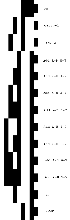
Below is a little program that just increments the B register. This is the form in which it would be printed out, with annotations added. This program can be seen running in this video.
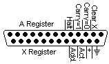
Since there is no screen other than the register display panel, and the registers are needed for calculations, what I really needed was another way of displaying data. To do this I plan to fit a printer. However, to connect the printer to the computer I first needed an external hardware port. I eventually decided on a parallel port as I have lots of them, and they have plenty of pins to connect things to. I decided on the pin layout as shown here:
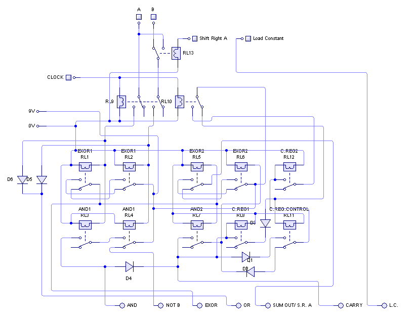
Once installed, I felt I needed a piece of external hardware just to test it. A printer is pretty hard to wire up in a hurry, so I started playing around with a few relays and a speaker. A few hours later, I had myself a sound card! It can play 16 different notes based on a binary number in the X register. The circuit diagram for it is below:
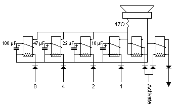
And here's the picture of the finished article:
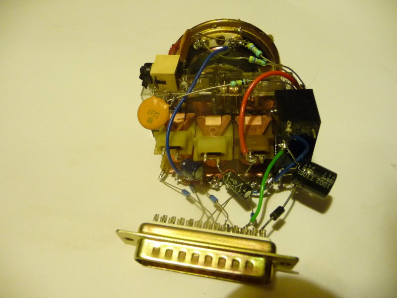
All the components are just hot melt glued to each other in a little bundle, and I am yet to fit a case or anything so it needs to be sat on something to stop it from flopping onto the floor. But it does work and produces about an octave and a half worth's of notes. I've only written one song for it so far, which is 'Mary had a little lamb'. The main reason I chose this song was that it was short and only has 3 notes so is easy to write. even so it was a good 2 meters of tape, even with high speed program format. You can hear it being played here.
I have also now started work on a robotic chassis which can be controled by TIM, however work on TIM has now slowed as I have started work on Tiny Tim. But don't worry, I won't forget about TIM... In fact I can't at the moment seeing as he's taken up residance in the center of my bedroom floor!
This project (and this page) is still a work in progress, so check back here for updates. Last update was on 03/07/12
For more pictures and diagrams of the inner workings, visit the gallery.
External links:
To see the above images and more please go to: http://imgur.com/a/hXnP3/all#0
For videos of TIM running please go to: http://www.youtube.com/rapidrory
And for more of everything go to: http://rapidrory2.blogspot.com/