I have always been a man of science, and as such i would usually have a rough understanding of how everything works. However one thing that had always bugged me was computers. I could never work out how a computer could turn 1's and 0's flowing through logic gates into what you see before you.
So in the summer of 2010 when I was just finishing my GCSE's, I decided to do a little research in to the matter. So I did a few searches on YouTube, and came across this video, which shows you how to make a simple 4 bit adding circuit out of transistors. It contains a circuit diagram in logic gates of how to make a simple half adder. Intrigued, I went out to the shed to try build the thing.
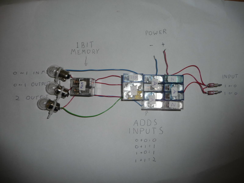
I had never been very good with electronics; the only circuitry I ever really had done was with relays, so I thought I'd try and apply some of the principles shown in the video using relays. I started by making up a few basic logic gates and wiring them together into a simple half adder as shown at the beginning of the video. I then worked out how to do basic latch memory. Lo and behold, TIM 1 was born. When I powered it up it would add 2 binary digits together. This was surprisingly satisfying seeing as it wasn't very impressive, but it meant I had finally grasped the very basics of computing.
This first attempt, as shown above, was the start of more than two years worth of design and development and sweating over a soldering iron until the small hours of the morning, but I'll come to all that later.
In the days following, a rush of developments and breakthroughs occurred (some of which seem painfully obvious); I discovered that an XOR gate and an AND gate would do the same as the 3 AND's, 2 NOT's and an OR as used in TIM 1 (which meant spending ages trying to develop an XOR gate made from just 2 relays), That two wires soldered together would make an or gate instead of having to use 2 relays, and that a diode could be used instead of my special 'Isolators'. All these developments meant less relays were used for any particular system. This was critical as I only have the relay's I can find lying around, I wouldn't go out and buy them as that costs money which I don't have. Not that there wasn't enough of them; my dad's an electronic engineer and there's loads of junk lying around which I could tare up for parts, It's just finding them that was the problem. This lack of relays was to become the bane of the entire TIM project.
Anyway, back to the project. TIM 2 was much the same as TIM 1, It just had another bit of memory. TIM 3 on the other hand was a 3 bit full adder, with control panel. This was where things began to get interesting.
I always remember the first time I switched it on. Not a particularly interesting event in theory, but just seeing that power light turn on and the power supply fan starting up gave the same sort of excitement I get when one of my vehicles moves under it's own power for the first time. It felt like a real computer, even if it was only capable of the most basic additions.
TIM 4 was much the same as TIM 3, just now it was a 4 bit full adder.
TIM 5 was my first attempt at a real computer (of sorts). I basically took TIM 4 and added 3 registers (memory blocks) ,a clock and a whole bunch of control circuitry. It looked awesome (in a kind of Heath Robinson-y way ) as I practically soldered up the relays where they happened to be at the time, meaning there was wires everywhere, Look at the picture below and you'll see what I mean:
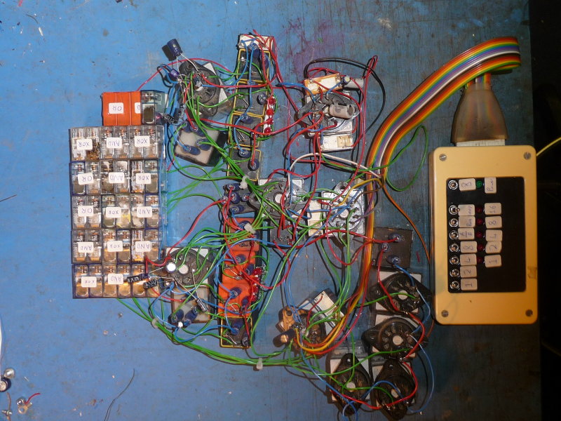
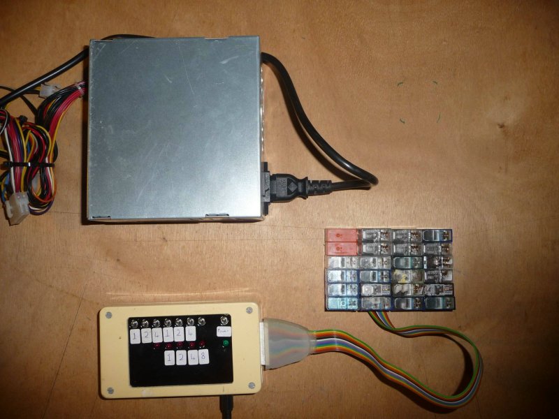
It could now do multiplication and incrementation as well as addition up to 31, however it was impossible to move anywhere as you had to move each relay individually. Here's a video of it incrementing up to 16. I eventually took it apart to make TIM 6, A more compact and simplified version of TIM 5 as shown below:
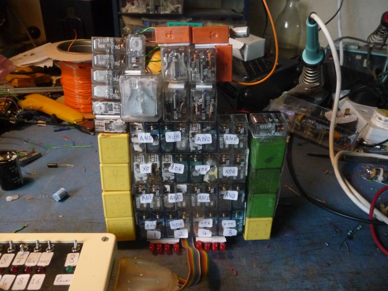
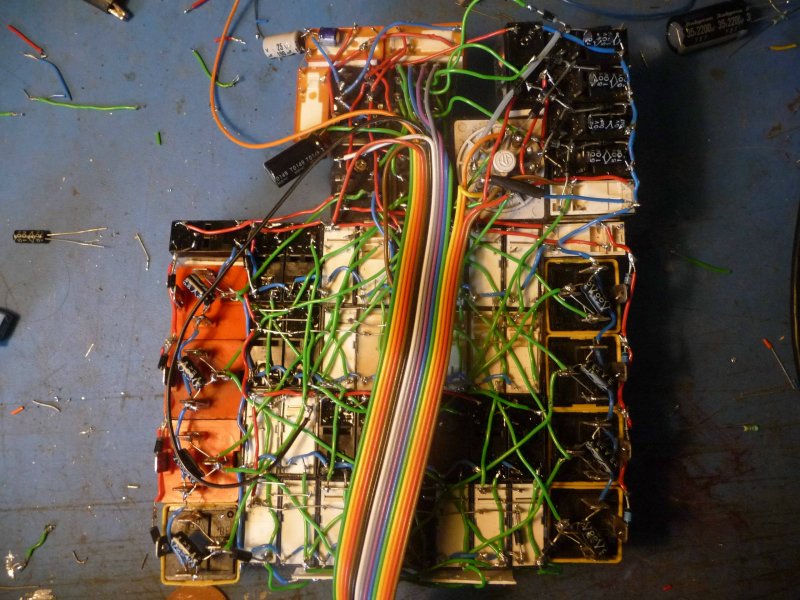
I've added the photo of the underside to just to give you an idea of the problems faced when trying to find bugs in the system. I never made any circuit diagrams for it since I made it up as I was going along, so I had to remember where all the wires went. There was one fault which caused it to go haywire occasionally which I never found until I finally disassembled it (one of the capacitors in the C register had become unsoldered for anyone who's interested).
Things started to get serious from now on. By this time I wanted a real working computer capable of running programs rather than just the simple calculators I'd been constructing. I started the design of TIM 7 at the end of the summer holiday's, and only finished the plans for it around Christmas. It was originally going to be a very simple 4 bit cpu, basically TIM 6 with punch tape instead of a control panel.
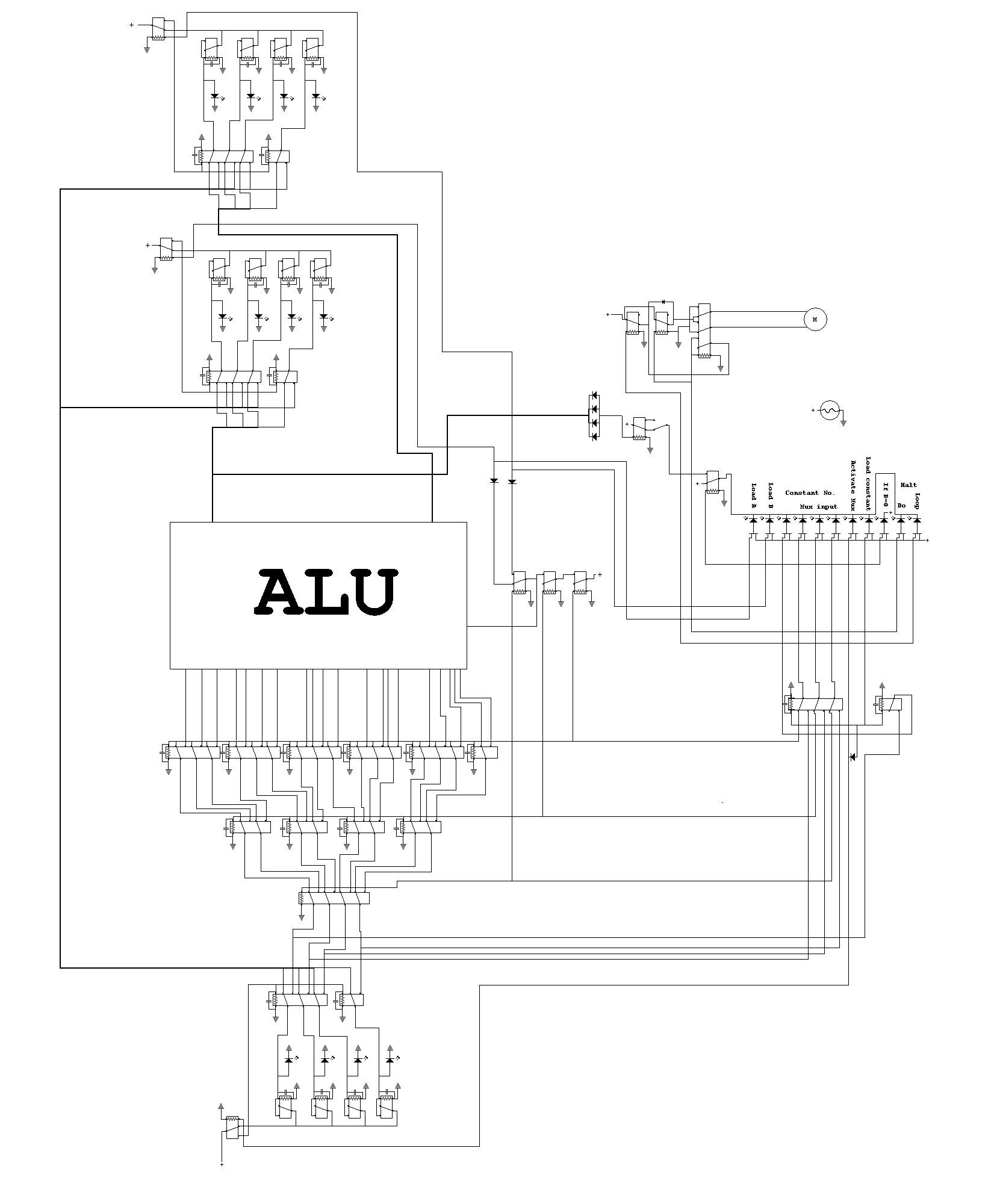
Then I upgraded the design to a full 5 bit punch tape computer with all the standard ALU commands, as shown below
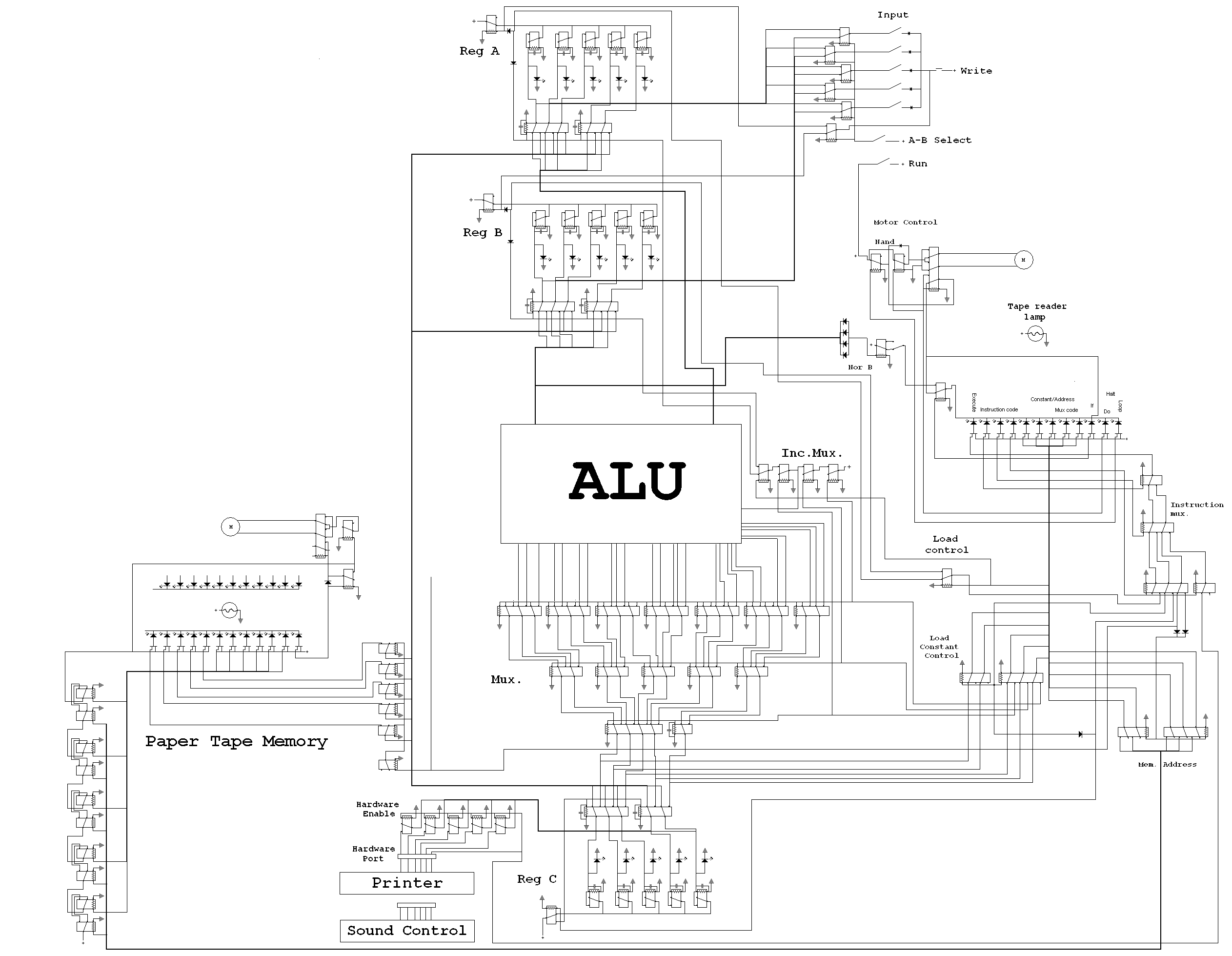
However I still didn't like the design all that much so completely redesigned it as a serial ALU, 8 bit punch tape computer which was much neater. Although TIM 7 was never built, I called the last one TIM 8, partly because TIM 7 had so many plans for it, and partly because it better suited an 8 bit computer.
As TIM 8 was a far more complex project, it gets it's own page: TIM 8