GALLERY
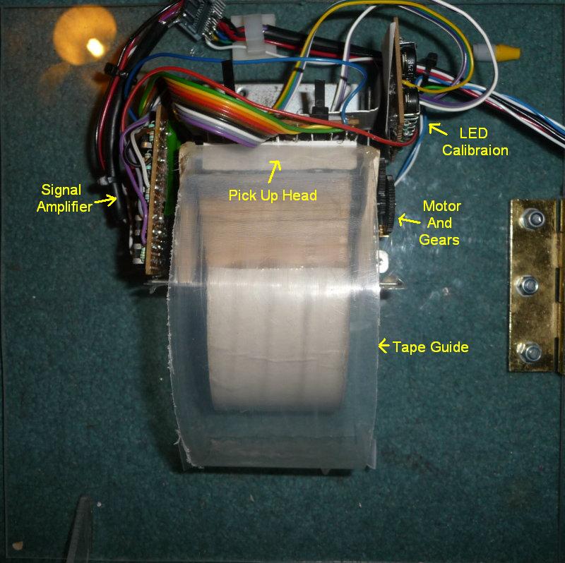
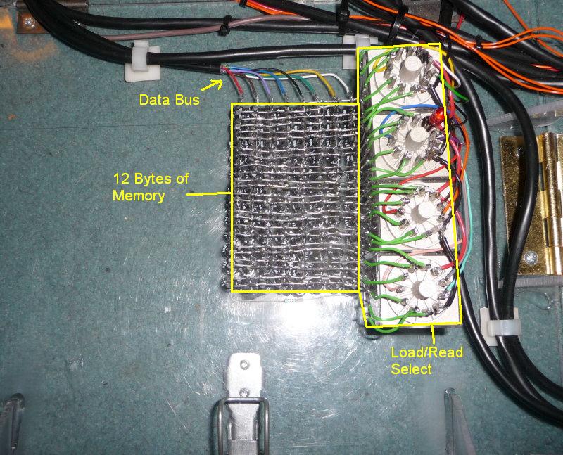
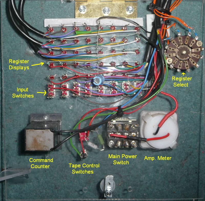
Here are some more detailed pics of the inner working's of TIM.
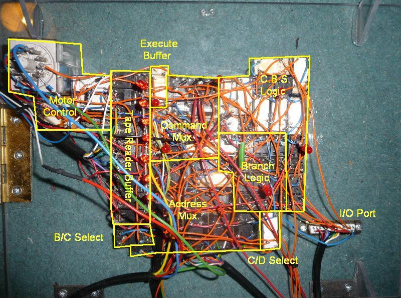
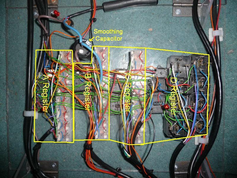
Below are pictures of each panel of the of TIM, each with lables to give you an idea of where everything is. ('Mux' just stands for Multiplexer)

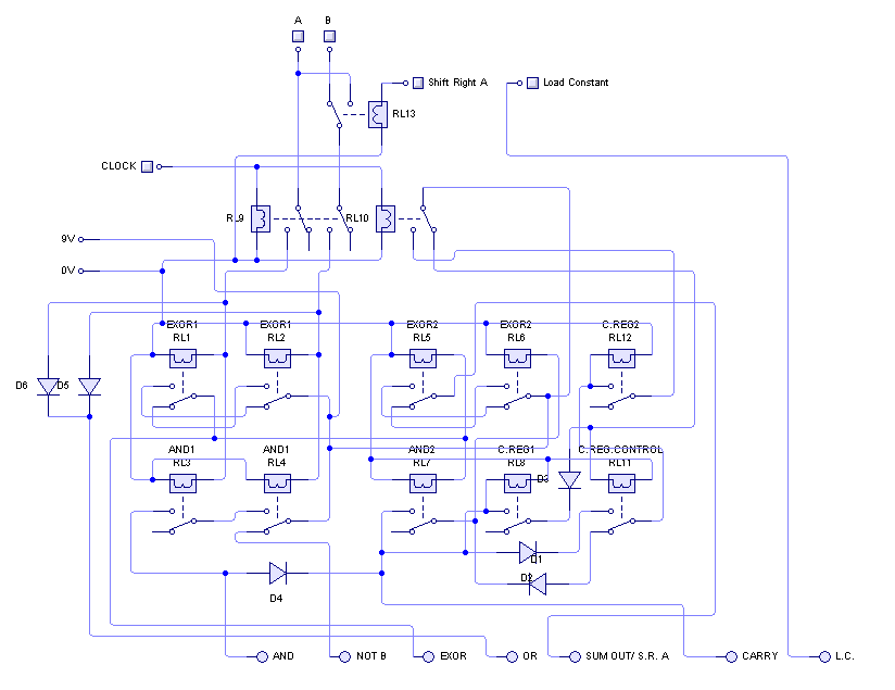
This is a picture of the actual circuit diagram for the ALU, showing all 8 function outputs. It was drawn up in Circuit Wizard, which was where the design for this ALU was finalized:
Here is the finished design of TIM 8. It is mostly accurate, appart from a few minor changes made during debugging. Sorry about it being so disorganised, but when I started it was not supposed to get this big!
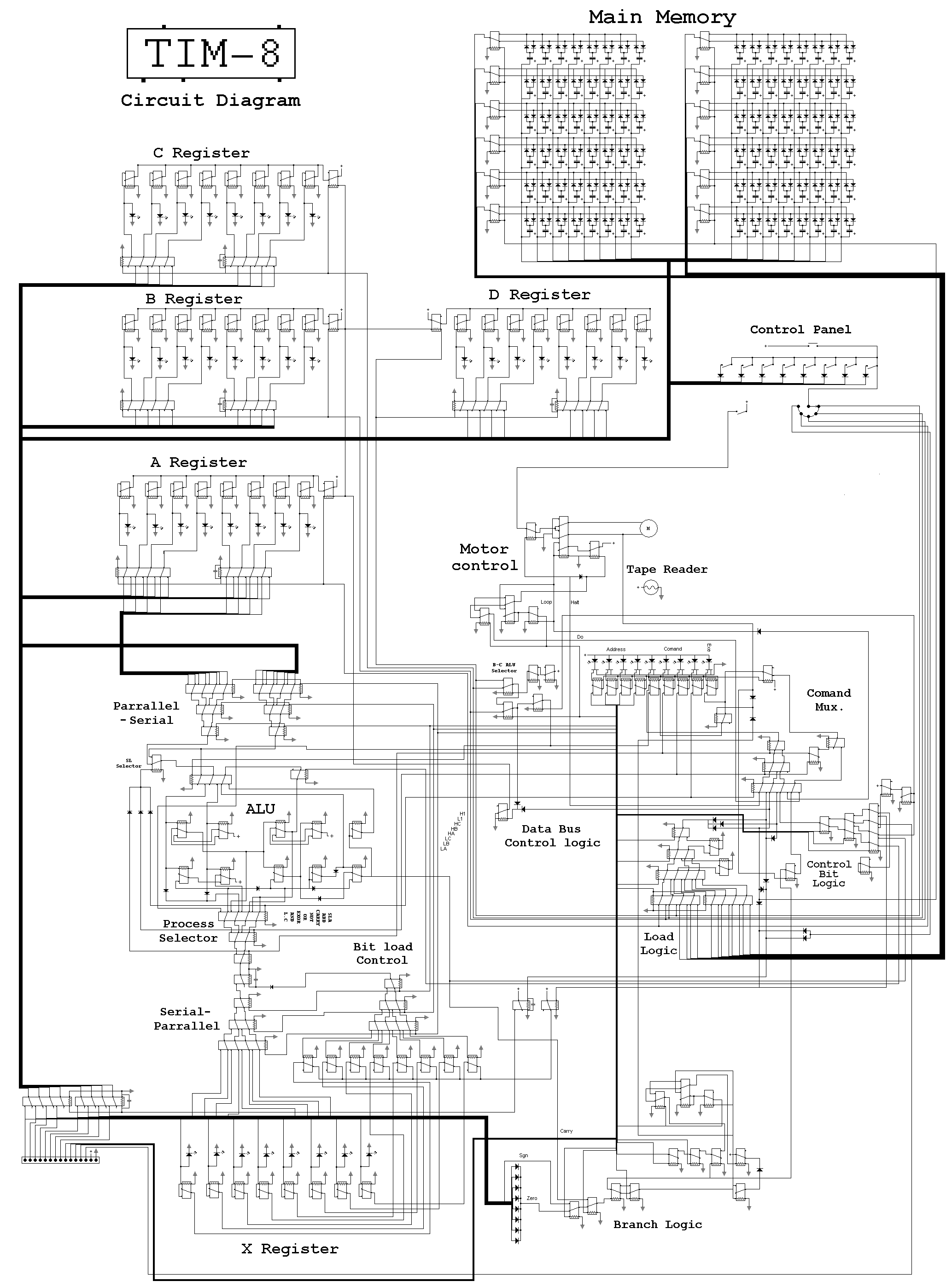
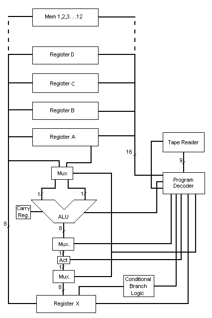
And this shows the general architecture of the whole system:
Here is the full list of T++ commands:
Do (1)
Loop (1)
Halt
Load to *
Load from *
Carry=0
Carry=1
Enable A
Disable A
Enable D
Disable D
Clear X
Act
If x<>0
If x=0
If x-
If x+
If carry=0
If carry=1
Endif
SL 0-7 *
ADD 0-7 *
CARRY 0-7 *
NOT 0-7 *
OR 0-7 *
EXOR 0-7 *
AND 0-7 *
LC 0-7 *
FUNCTIONS:
INPUT *
SUBTRACT * (from A)
INC *
(And any Binary Instruction
From BLT)
Any where where there is a *, either a memory locartion or register name is required. All ALU processes requiring 2 inputs take data from the A register and the register specified by the *
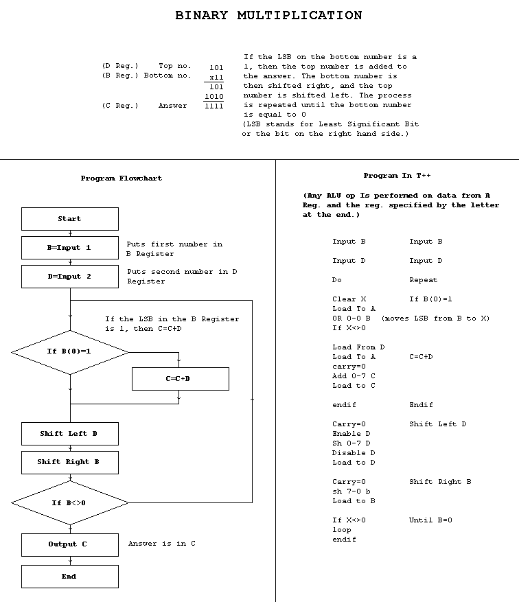
The image below demonstrates how binary multiplication works in T++: