Input/Output systems
Tape Reader
One major problem with many of these home made computers is that they often use an array of switches to input the program. This means that it takes an age to input a program of any length. To load a program onto Tiny Tim, I am looking into using the old tape cassette system. This will allow me to compile programs on my desktop, write them to cassette, and then load them into the computer. Alternatively I can just plug the two computer's directly together with an aux lead and program it straight across.
During the gap between finalising the design and actually buying some parts, I had some spare time, so I designed some hardware to read and write to the tape. I was originally going to use Manchester code to encode the data, however I couldn't work out a simple system to recover the clock pulse. So I came up with my own form of amplitude modulated code instead, the basics of which is shown below.
![]()
I may or may not use this system, but I have designs for both the encoder and decoder, so it should at least work to some extent.
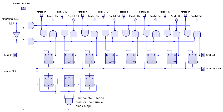
A single shift register is being used to convert the serial data to parallel and back, as it saves on components. Below is the circuit diagram for the shift register I plan to use.
Video output
I always joked about fitting a screen to TIM-8, but now I have a faster computer I thought it may actually be possible. So I've done some research into composite video signals, and found they're surprisingly easy to produce. Here's roughly what a monochrome signal for one horizontal scan looks like from the research I've managed so far:
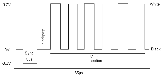
The screen takes 640 samples of the visible section and interprets the voltage as the luminance of the pixel. Therefore the signal above would give 6 alternating black and white stripes across the screen. To do grayscale the signal would be an analogue wave form rather than a square wave, but I'm only interested in the monochrome.
I was curious as to how accurate my interpretation was as I had read a lot of conflicting things during my research. So I got a composite signal to head phone jack cable, plugged one end into the headphone output of my computer and the other into a spare screen I had. I then drew up a wave form in Audacity and looped it several thousand times. As it could only be 65 microseconds long, the signal was very basic:
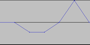
It roughly has a sync pulse at the beginning, followed by some visible data with no 'backporch' to calibrate the signal. I wasn't holding out much hope as it bore almost no resemblance to the correct waveform, but I played it anyway. To my amazement, I got the following image:
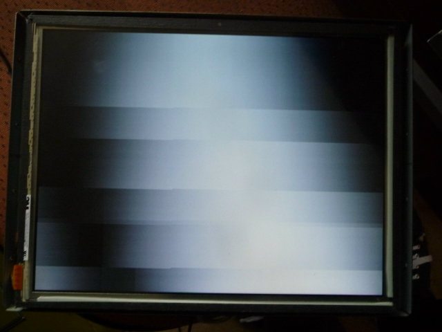
It was even roughly what I had drawn; an inverse 'V' shape which would produce a white stripe down the middle. This was very encouraging as it meant the signal did not have to be nearly as accurate as I previously thought. However, unfortunately for my computer, the experiment seems to have done bad things to my sound card. It now outputs a lot of noise, which makes rendering a video signal impossible, and is really irritating when you're using the normal speakers... But ah well, it's all in the name of science!
Ascii Display
Due to the relatively slow clock speed of Tiny Tim, the most pixels that could realistically be displayed with a composite video ouput would be 16x12. Considering the complexity of the circuitry required to drive a full display, I decided it was not really worth it.
However a while a go I found some LCD Ascii Displays, which take an ascii character code and display it on a little LCD screen. Since I only really wanted to use the screen for displaying text, It would be much easier to use one of these screens.
I haven't yet done any further research, but I will update this space when I get round to it.